TB 26-10 Printed Circuit Board Assembly Chip Resistor Body Cracking
For more information, contact Joel W. Sills, Langley Research Center, joel.w.sills@nasa.gov .
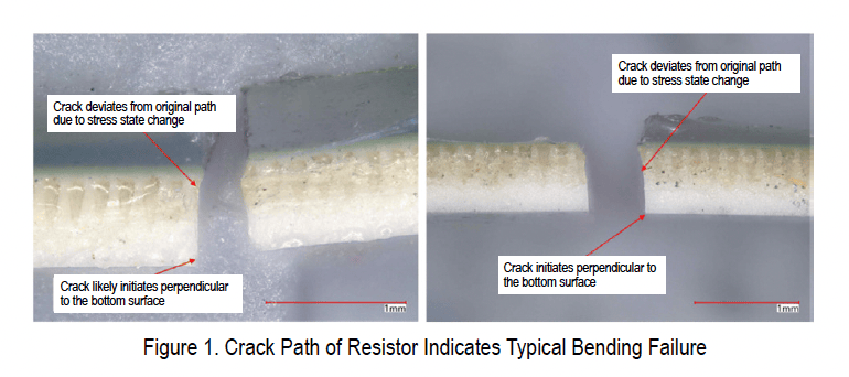
Failure Analyses Independent failure analyses concluded that the cracked chip resistors were due to bending/tensile failures. There was no clear-cut root cause or visible defect identifying a crack initiation site. Both resistors exhibited a single, straight crack across the short axis (perpendicular to the long axis), indicating a bending/tensile failure without twisting.
Guidelines for Assembly of Ceramic Body Components to Printed Circuit Boards The following guidelines are to be considered given the recent experience.
Read the original report
Opens NASA in a new tab